
The wafers of silicon that in the end develop into the chips in your smartphone include a single crystal. However that crystal has many faces, and it issues which of these faces is on the floor, the place transistors are made. In response to analysis introduced final month on the 2023 IEEE Worldwide Electron Machine Assembly (IEDM), the business won’t be utilizing the very best crystal orientation for upcoming units. By altering the crystal orientation, a crew at IBM Analysis achieved as a lot as a doubling of the velocity of constructive cost by means of transistors, although it got here at the price of a slight slowdown for detrimental cost.
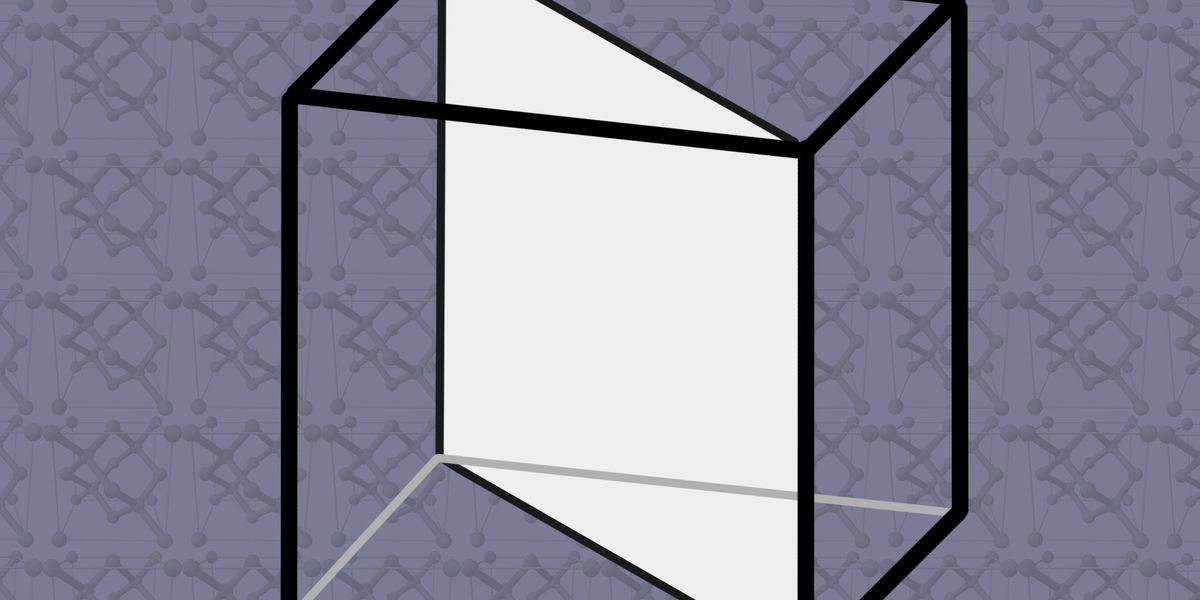
Crystals will be diminished to a unit construction that’s infinitely repeatable. For silicon, it’s a dice that appears prefer it’s bought a diamond caught inside it. There are silicon atoms at every nook of the dice in addition to on the middle of every face, and 4 extra atoms throughout the dice’s inside. Right this moment’s transistors, FinFETs largely, are constructed on silicon whereby the highest of that dice is the floor of the wafer. Specialists name that crystal orientation “001.” Silicon wafers with the 001 orientation “are utilized in many superior logic applied sciences, together with in IBM’s 2-nanometer chip know-how,” says IBM Analysis’s Shogo Mochizuki.
However Mochizuki and his colleagues say that as chipmakers transition to the following kind of transistor—the nanosheet or gate-all-around system—they may get higher outcomes in the event that they used the “110” orientation as a substitute. That’s primarily a slice vertically by means of the dice.
Why would that make any distinction? It has to do with how briskly cost can journey by means of the silicon lattice. Within the CMOS circuits that make up logic chips, each electrons and holes—positively charged electron vacancies—should move. Usually, electrons are the zippier selection, so the comparatively poky mobility of holes is a limiting issue when chipmakers design ever smaller transistors. And it’s already recognized that holes transfer quicker when touring the 110 aircraft than the 001. The other is true for electrons, however the impact is smaller.
Right this moment’s FinFETs already reap the benefits of the quicker journey in that aircraft. Though they’re made utilizing 001 silicon, the transistor’s channel area—the half the place present flows when the system is on, or is blocked when it’s off—is a vertical fin of fabric within the 110 aircraft, perpendicular to the silicon floor. However in nanosheets, present has to move by means of constructions which might be parallel to the silicon floor, within the hole-slowing 001 aircraft.
Mochizuki’s crew constructed matching pairs of nanosheet transistors on each 001 and 110 silicon wafers. Each sorts of transistors—hole-conducting pFETs and electron-conducting nFETs—have been current. Along with the totally different crystal orientations, the transistors had quite a lot of totally different traits to check: Some had skinny sheets, some thicker; some had lengthy channels, some shorter. The 110 pFETs outperformed their 001 brethren, although the magnitude of the impact typically diverse in line with the thickness of the silicon nanosheets. As anticipated, the nFETs labored barely worse in 110 silicon. However the enhance to the pFET efficiency is sufficient to make up for that, the researchers recommend.
Don’t search for business to shortly swap to 110 silicon. “Technically, it’s potential,” says Naoto Horiguchi, CMOS system know-how program director at Belgium-based Imec. However there are sufficient variations in the best way that layers of silicon and silicon germanium are grown on the totally different crystal orientations that it will “require cautious engineering,” he says.
Mochizuki says IBM plans to discover a approach to cut back the ailing results of the choice orientation on electron conduction. Moreover, the crew will discover 110 silicon’s use in 3D-stacked nanosheet transistors referred to as complementary FETs (CFETs). This system structure usually stacks an nFET on high of a pFET to chop down the scale of logic circuits. Such stacked units are anticipated to roll out inside 10 years, and all three advanced-logic chip producers reported prototype CFETs final month at IEDM. Mochizuki says the IBM crew might attempt constructing the pFET half from 110 silicon and the nFET from 001.
From Your Website Articles
Associated Articles Across the Internet