Experimental Dedication of the Results of Slicer Settings on the Mechanical Energy of Fused Filament Fabrication Manufactured Specimens
Samuel Hart and Trevor Grey
Mechanical Engineering
Valparaiso College
Valparaiso, Indiana
Dr. Daniel Blood
Assistant Professor of Mechanical Engineering and Bioengineering
Valparaiso College
Valparaiso, Indiana
ABSTRACT:
The patron-level Fused Filament Fabrication (FFF) neighborhood has little scientific info out there on the mechanical properties of printed components. Even much less is understood in regards to the relationship between slicer settings, corresponding to hotend temperature, and the ensuing mechanical power with varied filaments. This paper presents a proposed technique of characterizing the connection between slicer settings for various filament sorts and the ensuing mechanical power of FFF components. Moreover, outcomes of testing MatterHackers’ MH Construct PLA, PRO Collection PLA, PRO Collection ABS, PRO Collection PETG, PRO Collection Nylon, and NylonX filaments are reported. It’s discovered that NylonX has the best power to weight ratio at 92 lbf/g, MH Construct PLA has the best peak load at 478 lbf, and PRO Collection Nylon has the best ductility of the filaments examined with 25.6% pressure at failure. PRO Collection PLA power depends the least on the path of the utilized pressure with an isotropic score of fifty%. Extra parameters, corresponding to half fan pace, print pace, and infill proportion, are examined to find out their impact on tensile power.
1. INTRODUCTION
1.1 Motivation
The expiration of Stratasys’ Fused Deposition Modeling (FDM) patent in 2009 resulted in a beforehand unimaginable explosion in do-it-yourself (DIY) tech [1]. The open-source neighborhood renamed the printing course of Fused Filament Fabrication (FFF) to forestall infringement on Stratasys’ FDM trademark. Filament based mostly 3D printing maintains its place as the first printer know-how for shoppers because of the relative low value of entry, and the worldwide help neighborhood. The aggressive FFF printer market adjustments at a staggering tempo from 12 months to 12 months, and new capabilities are allowed by this new tech. Improvements in printer {hardware} and new sorts of filament present customers with an ever-expanding array of choices. Whereas many of those improvements are designed to make printers extra user-friendly, many extra declare to supply the ‘finest’ prints potential; nevertheless, and not using a scientific comparability of the options it is unimaginable to validate these claims. The analysis group at Valparaiso College (Valpo) acknowledges that there’s a want for unbiased analysis of printer elements and consumables, and the group has spent two years creating a repeatable technique of analysis.
[1] Crump, S. Scott, “Equipment and Methodology for Creating Three-Dimensional Objects,” U.S. Patent 5 121 329, 9 June 9, 1992.
1.2 Figuring out Components that Have an effect on Printed Components
A objective for many 3D printing fans is to supply components which might be aesthetically pleasing, and have comparatively excessive mechanical power. Sadly, these two desired traits might not be potential with the identical printer/filament/slicer setting combos, and solely the person printing the half can decide if they need perform, kind, or a mixture. An extra problem with quantifying aesthetics is the subjective nature of attractiveness. Determine 1 reveals an instance of two prints that come from the identical mannequin and total settings, however with a distinction within the .STL decision leading to ‘easy’ and ‘low-poly’ prints. Because of the subjective nature of aesthetics, the Valparaiso College analysis group is specializing in quantifying mechanical properties.
 and low-poly (right).")
Determine 1. Examples of snowman prints in excessive decision (left) and low-poly (proper).
Step one in evaluating power is figuring out failure modes of printed components. Preliminary tensile testing of FFF specimens reveals three main modes of failure: yielding of the fabric, delamination between Z-layers, and delamination within the X-Y path. Subsequent, course of parameters are recognized which will contribute to failure for every of the three modes. The next conclusions are based mostly on evaluation of the failed specimens, evaluation of slicer settings, and comparability of printer elements.
1.2.1 Failure Resulting from Yielding
Yield power is outlined because the transition from elastic (recoverable) deformation to plastic (everlasting) deformation [2]. Within the case of an injection molded half, that is largely because of the materials properties of the polymer, and the interior residual stresses on account of the injection course of. FFF printing is just like injection molding on this respect, however adjustments in materials properties and the bodily means of producing inner residual stresses are distinctive. Extruded materials properties are principally a perform of the polymer sort, however the materials properties are additionally affected by the extent of polymer degradation. This degradation of the polymers can happen from moisture, ultra-violet (UV) gentle, chemical substances, and most notable for FFF printing, heating. Some degradation possible happens earlier than the consumer receives the filament because of the potential use of recycled plastics, and heating of the polymer on the time of filament manufacturing. Additional degradation can happen on the consumer’s finish from improper filament storage, or overheating throughout extrusion. Consequently, the three gadgets recognized as vital for materials properties are filament sort (materials, producer, and storage historical past), extruder-hotend-nozzle mixture, and slicer settings (hotend temperature and extrusion price).
Inside residual stresses are attributable to the uneven cooling of a fabric. Injection molded components usually cool faster on the surface surfaces as in comparison with the within. The polymer turns into extra inflexible and contracts because it cools; consequently, if the surface floor cools too quickly the interior materials could have no solution to freely contract. Determine 2 reveals an instance of this phenomenon with a visual dip within the injection molded half floor. This leads to a non-zero state of stress within the half earlier than any exterior masses are utilized, and finally will have an effect on the yield power. FFF printed components expertise the same inconsistency in cooling, however it’s attributable to the delay between extrusion of the layers. New layers are extruded at a better temperature than the cooled earlier layer, and when the brand new layer cools it is going to trigger a contraction of each layers. Determine 3 demonstrates warping of printed components that generally happens and not using a heated mattress or managed environmental circumstances. Printing on a heated mattress or controlling ambient temperatures permits every layer to chill to a better ambient temperature, and thus leads to a extra constant cooling of layers and diminished warping. The first gadgets recognized as vital for inner residual stresses are filament sort (materials), printer ambient circumstances (heated mattress and heated chamber), and slicer settings (hotend temperature and extrusion pace).
[2] Beer, Ferdinand P., et al., Mechanics of Supplies, McGraw-Hill Schooling (India) Personal Restricted, 2017.

Determine 2. Dip within the floor of a roll of filament as a result of contraction throughout uneven cooling.

Determine 3. Warping of printed half on the construct floor.
1.2.2 Failure Resulting from Delamination within the Z-Route
Delamination of Z-layers, as seen in Determine 4, happens when there may be inadequate bonding between printed layers. This can be a results of incorrect extrusion temperature leading to a chilly joint, extreme contraction between layers, or from international contaminants stopping correct physiochemical adhesion. The recognized causes of delamination are primarily because of the filament (materials, producer, and storage historical past), extruder-hotend-nozzle mixture, printer heating functionality (mattress and chamber), and slicer settings (hotend temperature).

Determine 4. Delamination of PLA specimens within the z-direction.
1.2.3 Failure Resulting from Delamination within the X-Y Route
Geometric accuracy of injection molded components is closely influenced by the standard of the mildew and the cooling of the components after injection, however FFF print accuracy relies on the flexibility to exactly management the place and quantity of filament extruded. The right amount of the fabric have to be extruded within the appropriate location for every layer. The fabric is extruded in traces that could be parallel or overlap different extruded traces. The standard of the line-to-line bond is vital to forestall extruded traces from separating underneath load. Slicing software program usually modifies the extruder path to create overlap between outlines and infill to advertise adhesion, but when the extrusion settings are incorrect there could also be inadequate materials extruded to permit correct bonding between the respective extruded traces. The recognized variables affecting delamination within the X-Y path are filament (materials, producer, and storage historical past), extruder-hotend-nozzle mixture, printer movement system accuracy/repeatability, and slicer settings (hotend temperature, define overlap, and extrusion multiplier).
1.3 Testing Parameters for Section One
Desk 1: Failure modes and recognized causes of failure.
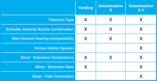
Desk 1 reveals a abstract of the earlier part evaluation. The seemingly limitless mixture of the above elements makes it impractical to check each potential variable without delay. The Valpo group acknowledges that many shoppers are financially restricted on {hardware} modifications, and the buyer neighborhood will profit extra from a information on free software-based adjustments to their printing course of. The group additionally recognized the significance of performing early exams with generally utilized elements in order that outcomes usually tend to apply to a typical consumer’s setup.
1.4 Testing ‘Dumbbell’ Specimens

Determine 5. FFF printed ‘dumbbell’ specimens.
The primary specimen geometry examined is the ASTM D412-06a ‘dumbbell’, as seen in Determine 5. This testing customary evaluates tensile properties of each thermoplastic elastomers and vulcanized thermoset rubbers. This customary was initially chosen to permit testing of inflexible filaments like PLA, and versatile filaments like TPU/TPE.
Preliminary exams with the ‘dumbbell’ specimen reveal that the geometry could also be efficient for testing polymer/elastomer sheets, however it’s not conducive for FFF printed half testing. The geometry’s faults are as follows:
- The specimen have to be clamped on each ends for tensile exams, and this restricts the consumer to 100% infill of the ends to forestall crushing.
- Any misalignment of the specimen within the testing equipment leads to non-uniaxial forces that contribute to inconsistent peak specimen masses.
- Printing the specimens in a vertical orientation leads to a comparatively tall and slender print that’s vulnerable to geometric printing errors on the prime.
- The vertical association additionally leads to stacked potential failure factors, and the weakest layer bond controls the breaking power.
- The scale of the specimen limits variation within the p.c infill, variety of outlines, and variety of prime/backside layers.
- The space between the highest floor of the printed half and the printer mattress is a number of orders of magnitude totally different for vertical and horizontally printed specimens. The distinction partially heating can have an effect on the bond power, and this may lead to non-equivalent comparability of the 2 print orientations.
- Few horizontally oriented specimens might be printed at one time so it reduces batch specimen print measurement.
These shortcomings reveal the necessity for a brand new specimen geometry to correctly characterize the FFF course of.
2. EXPERIMENTAL SETUP
2.1 Tensile Specimen Geometry
The inherent variability of FFF 3D printers made it difficult to pick the specimen geometry that leads to probably the most constant tensile testing. The objective is to search out probably the most acceptable specimen geometry the place the outcomes might be extrapolated to a number of hotend and printer combos. Desired properties of the brand new specimen are:
- The power to print the specimen in numerous orientations with out frequent printer limitations affecting the specimen power.
- A geometry that permits for a large number of slicer settings to vary the ensuing printed specimen.
- Comparatively low specimen quantity to reduce print time and value.
- Comparatively small footprint to allow massive batch sizes.
- Ease of elimination from printer mattress to reduce the impact of specimen dealing with.
- Skill to reduce non-uniaxial forces produced from misalignment within the tensile testing equipment.

Determine 6. Technical drawing of recent specimen.
 and post-testing PETG specimen (right).")
Determine 7. New specimen design loaded in MTS QTest 150 tensile testing machine. View of the customized loading pins within the MTS machine (left) and post-testing PETG specimen (proper).
The brand new specimen design, as proven in Determine 6 and seven, overcomes the challenges found within the first set of exams in a number of methods. First, the brand new specimen geometry self-aligns when performing tensile testing as a result of using loading pins as an alternative of clamps. This additionally eliminates the necessity for clamping onto stable sections of the specimen. The brand new loading course of introduces a better degree of repeatability and reduces the cycle time for exams. The specimen form can also be designed with slicer settings in thoughts; particularly, prime/backside layers, variety of outlines, and p.c infill. The thicker specimen permits for a wider vary of those settings to be examined on the identical geometry. The print space decreases from 2500 mm2 to 1100 mm2, and the stable physique quantity stays comparatively low at 7000 mm3. Lastly, the form permits for the components to be printed in quite a few configurations with out requiring important helps, or rising the size to thickness ratio excessively.
2.2 Printing {Hardware} and Filament
The Prusa i3 MK2 printer is used because the testing {hardware} because of the sub $1000 price ticket, a direct-drive extruder, a heated mattress, real E3D-V6 hotend, and auto-leveling {hardware}. Additionally, there isn’t a enclosure to guard the specimen or printer from the house atmosphere. This enables for extra generalization as most funds client printers should not have enclosures. Sooner or later, an enclosure will likely be added so the advantages of environmental safety from disturbances, corresponding to drafts from an AC vent, might be quantified. The printers have been assembled by one particular person on the group. The one modification made to the printers is exchanging the brass nozzle for a hardened metal nozzle of the identical diameter when printing NylonX. That is executed to forestall put on in order that the brass nozzles can be utilized for future specimens.
MatterHackers’ filament is used for the testing as a result of its widespread use, availability of filament sorts, and their filament particular solutions for baseline slicer settings. Within the title of transparency it also needs to be famous that MatterHackers donated filament to help this analysis, however all outcomes are absolutely generated by the Valparaiso College group with out modification.
2.3 Batch Printing Configuration
Ten specimens are printed in every batch to restrict print time whereas sustaining smaller printer compatibility. Extra batches are printed after the ‘finest’ extrusion temperature is decided to cut back uncertainty. A complete of thirty specimens are produced for the ‘finest’, ‘finest’+5 ˚C, and ‘finest’-5 ˚C extrusion temperatures respectively. Structure of the specimens, as seen in Determine 8, is dictated robotically by Simplify3D. This eliminates the prospect of inconsistent spacing when creating new print recordsdata. Specimens and unused filament are saved inside a Ziploc WeatherShield 26.5 Quart Storage container with a 1.7 lbm silica gel desiccant bead canister till testing or printing. Tensile testing is often accomplished inside 3 days of printing the specimens.

Determine 8: Simplify3D format of ten tensile specimens on a Prusa i3 MK2.
2.4 Slicer Software program
Simplify3D is used because the slicer software program as a result of its versatility with setting decisions and its reputation amongst shoppers. All baseline parameters are pulled from the MatterHackers on-line information. If a spread is given then the imply worth is used. Testing focuses closely on figuring out the ‘finest’ hotend temperatures for every respective filament. That is outlined because the minimal temperature the place the tensile power stays comparatively fixed no matter a rise within the extrusion temperature. The bottom worth is reported to reduce oozing/zits frequent with larger extrusion temperatures. Probably the most acceptable hotend temperature is a hotly debated subject throughout the printing neighborhood; nevertheless, numerous variables can have an effect on the ‘finest’ temperature for every filament sort. The hotend temperature is the one parameter various within the first set of exams. Extra exams are carried out after the ‘finest’ hotend temperature is decided. These exams concurrently differ totally different parameters to find out tensile power sensitivity.
All of the prints are carried out utilizing an SD card for g-code switch. Inconsistent switch of the g-code to the printer from a pc can come up as a result of connection or software program points, and using a SD card eliminates that extra variability.
3. TESTING METHODOLOGY
3.1 Verification of Equal Printer Assumption
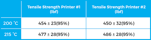
Two Prusa i3 MK2s are used on this part to expedite testing. It’s essential to validate the null speculation that any distinction within the tensile power between the 2 printers is because of the inherent variability within the course of. These exams used a single roll of black MH Construct Collection PLA printed at 200 °C and 215 °C respectively. Outcomes for these take a look at are proven in Desk 2. A two-way evaluation of variance is performed on the tensile power of the specimens after tensile testing. The impact of utilizing two separate printers shouldn’t be statistically important on the 0.05 significance degree (F ratio = 0.024, p>0.05). The statistically insignificant distinction justifies the transfer to deal with variability launched by the 2 printers as negligible
Desk 2: Tensile take a look at outcomes to find out whether it is acceptable to think about the printers as equal.
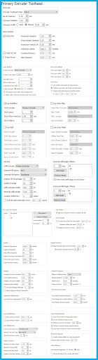
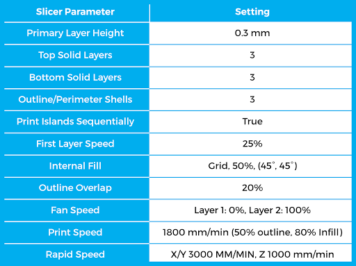
A choice of the baseline slicer settings for the printed specimens are listed in Desk 3, and detailed screenshots of settings are offered within the appendix. Non-filament particular settings, corresponding to print pace, are generated from the Prusa i3 MK2 profile on Prusa’s official web site. Any remaining settings are chosen from previous expertise and data from the Valpo group.
Desk 3: A choice of the slicer baseline slicer settings used within the first set of exams.
3.3 Dedication of Minimal Hotend Temperature
Minimal hotend temperature for every sort of filament is decided from evaluation of each the height load and power to weight ratios. Most temperature exams begin at 15 °C under the MatterHackers common advisable hotend temperature; nevertheless, in some circumstances after knowledge is reviewed, it might be decided that the minimal hotend temperature shouldn’t be reached. In these circumstances, hotend temperature is dropped by 5 °C for each batch till both the minimal temperature is discovered, or print failure happens (e.g. delamination within the z-direction throughout printing).
3.4 Tensile Testing Process
After a batch of specimens finishes printing, it’s positioned in a Ziploc WeatherShield 26.5 Quart Storage container with a 1.7 lbm silica gel desiccant bead canister inside for not less than 8 hours. Specimens are examined at room temperature, 70 ± 5 °F. When sufficient specimens are printed, every batch is then weighed with an AWS-100 scale, and the common recorded. Specimens are loaded right into a MTS QTest 150 tensile machine through the loading pins which begin with a center-to-center distance of roughly 19 mm. A relentless elongation price of 5 mm/min is utilized when testing begins. This testing pace is predicated off the ASTM customary mentioned beforehand. A 33700 lbf (150 kN) MTS load cell is used to measure the utilized load, the displacement is predicated on the body readings, and the information is collected by a Dell Optiplex 990 PC at 60 Hz.
4. RESULTS
4.1 Hotend Tensile Outcomes
Desk 4: Tensile take a look at outcomes for MatterHackers filament. Values signify the common for specimens printed at or above the minimal advisable hotend temperature.
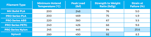
A comparability of the experimentally decided tensile properties for every respective filament sort is offered in Desk 4. The desk compares prints of MatterHackers MH Construct PLA, PRO Collection PLA, PRO Collection PETG, PRO Collection ABS, PRO Collection Nylon, and NylonX. The height load, power to weight ratio, and pressure at failure are all averages of specimens that meet or exceed the minimal advised hotend temperature. The items of lbf/g are chosen for the power to weight ratio as a result of customers’ familiarity with lbf and the frequent follow of measuring filament/prints in grams.
These numbers usually are not meant to foretell the power of a consumer’s particular printed half. The outcomes are merely used to find out the relative power of 1 filament to a different. This enables a wider viewers to use the teachings discovered in the direction of their very own prints. The advanced nature of FFF printed components requires a extra advanced evaluation of stress concentrators, loading path/sort/price, and the results of working temperature/humidity/age/and so on… to find out the mechanical properties of a selected half.
4.1.1 Black MH Construct PLA
MatterHackers Black MH Construct PLA is the primary filament examined. Determine 9 reveals the hotend-temperature power to weight ratio (S-W) curve for Black MH Construct PLA. The plot reveals that a rise from 185 °C to 200 °C yields a 43% improve within the power to weight ratio. The graph reveals that after 200 °C the height load stays comparatively fixed; consequently, the advisable minimal hotend temperature for Black MH Construct PLA is 200 °C.

Determine 9: MatterHackers Black MH Construct PLA hotend temperature comparability for a horizontal specimen print orientation.
4.1.2 Black PRO Collection PLA
Determine 10 reveals the outcomes for MatterHackers Black PRO Collection PLA. It’s anticipated that PRO Collection PLA will carry out just like the MH Construct PLA, and above the 200 °C mark the 2 supplies produce comparable outcomes; nevertheless, PRO Collection PLA didn’t expertise the drop off in power under 200 °C. The authors suggest printing with not less than 200 °C for this specific printer setup because of the slight improve within the S-W ratio; nevertheless, it doesn’t seem that there will likely be a big discount within the half power for this testing orientation under 200 °C.

Determine 10: MatterHackers Black PRO Collection PLA hotend temperature comparability for a horizontal specimen print orientation.
4.1.3 Black PRO Collection ABS
Black PRO Collection ABS filament produced the weakest prints with most failing under 400 lbf. Determine 11 reveals the inconsistent S-W ratio development for the examined hotend temperatures. One concern with printing the ABS specimens is that warping of the specimens happens for many batches. It’s potential that the specimens carry out poorly throughout tensile testing as a result of residual stresses induced by the uneven cooling, and a rise within the ambient temperature may scale back this impact. Extra exams past the preliminary ten specimens usually are not carried out because of the challenges in printing ABS with the present setup. The Valpo group is hesitant to make a suggestion with out extra exams in an elevated temperature printing atmosphere, however the specimens printed at 220 °C demonstrated the best peak load and biggest ductility; subsequently, that’s the present advised minimal hotend temperature.
Future exams on all filament sorts will reveal what enhancements within the tensile power are available with an elevated ambient temperature.

Determine 11: MatterHackers Black PRO Collection ABS hotend temperature comparability for a horizontal specimen print orientation.
4.1.4 Purple PRO Collection PETG
Purple PRO Collection PETG outcomes, as proven in Determine 12, reveal a rise within the S-W ratio from 235 °C to 240 °C, after which a comparatively fixed S-W ratio above 240 °C. This leads the Valpo group to recommend a minimal hotend temperature of 240 °C. You will need to be aware that though PRO Collection PETG has a decrease S-W ratio as in comparison with PLA, it didn’t fail in a brittle method. PRO Collection PETG specimens usually stayed intact, and had roughly double the elongation earlier than failure as in comparison with PLA. This improve within the elongation result in an roughly threefold improve within the toughness because of the form of the stress-strain curve. The upper extrusion temperature and slight variability of samples leads the Valpo group to hypothesize that extra positive factors in power could also be discovered with a rise within the ambient print temperature.

Determine 12: MatterHackers Purple PRO Collection PETG hotend temperature comparability for a horizontal specimen print orientation.
4.1.5 Blue PRO Collection Nylon
Nylon is extensively thought-about as a comparatively ductile polymer. MatterHackers Blue PRO Collection Nylon carried out as anticipated with the best ductility score of all filaments by greater than 100%. PRO Collection Nylon’s most fascinating attribute is its failure modes. At decrease hotend temperatures PRO Collection Nylon’s layers delaminate inflicting peak load functionality to drop. The delamination impact disappears after a hotend temperature threshold of 245 °C is obtained, and the failure mode transitions right into a extra anticipated yielding failure. Each PRO Collection PETG and NylonX expertise the delamination failure, however the Nylon filament requires a better hotend temperature earlier than the failure mode dies out. Determine 13 reveals that the S-W ratio dips at 250 °C and the Valpo group believes this is because of a single 10 specimen batch that exhibited decrease S-W ratios as in comparison with the opposite batches at 250 °C. The advised minimal hotend temperature for PRO Collection Nylon on this specific setup is 245 °C.

Determine 13: MatterHackers Blue PRO Collection Nylon hotend temperature comparability for a horizontal specimen print orientation.
4.1.6 NylonX
Maybe probably the most fascinating filament take a look at outcomes are MatterHackers’ NylonX. There may be important problem bonding the z-layers of NylonX at low hotend temperatures. The group attributes this to an open print mattress atmosphere fairly than an enclosed chamber. The S-W ratio of NylonX is the bottom of all filaments examined on the low temperature finish, however it achieves the best score after the 260 °C mark. Using a hardened metal nozzle of 0.4 mm allowed the group to protect the brass nozzles for testing continuity, however the decrease thermal conductivity of the metal limits warmth switch to the filament. To rectify this, the group printed at larger hotend temperatures than different filaments. Determine 14 reveals that rising the hotend temperature from 255 °C to 260 °C leads to a 55% improve within the S-W ratio. The advised hotend temperature for NylonX with a hardened metal nozzle is not less than 260 °C.

Determine 14: MatterHackers NylonX hotend temperature comparability for a horizontal specimen print orientation.
4.2 Extra Assessments
Figuring out minimal hotend temperatures is a crucial facet of FFF printing, however it doesn’t embody all the elements that have an effect on print power. The Valparaiso College group realizes that the tensile power of components printed within the earlier part are depending on extra elements corresponding to half fan cooling, z-layer top, variety of outlines, variety of prime/backside layers, infill proportion, and print pace. An in-depth evaluation of all these elements would require a paper of its personal, however these preliminary outcomes ought to help customers in making extra knowledgeable choices about their slicer settings.
4.2.1 Half Fan Cooling
Desk 5: Tensile outcomes for half fan exams with Black MH Construct PLA.

The usage of a component fan can improve the capabilities of a printer throughout bridging operations or for areas with steep angles, however it additionally could have an effect on the flexibility for layers to bond. Testing this impact on the tensile power first requires figuring out the minimal hotend temperature, after which printing a batch of thirty specimens in Black MH Construct PLA with the half fan off. Desk 5 reveals that printing with the half fan off produces a statistically important impact on the height load; nevertheless, the rise in power is simply 5%. The fan’s low affect on half power signifies that the fan can be utilized with a statistically important, however minimal impact on the power of PLA components.
4.2.2 Layer Top
Lowering the layer thickness can have a optimistic impact on the beauty look of a printed half, however it could possibly additionally improve the general print time. These are comparatively straightforward outcomes to foretell with fashionable slicer outputs, however the impact on mechanical power with totally different layer thicknesses is unknown.
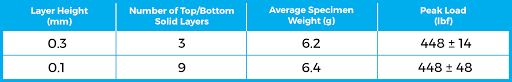
Specimens from part 4 are printed with 0.3 mm layer heights to lower the general print time. Extra exams are run with 0.1 mm layers to find out if the thinner layers have a statistically important impact on the tensile power. One extra modification to the baseline g-code is to regulate the variety of prime and backside stable layers. That is an try to take care of the general thickness of the stable layers on the highest and backside of every tensile specimen.
Desk 6 reveals the outcomes of the layer top take a look at, and the 0.3 mm and 0.1 mm tensile outcomes are statistically comparable. Extra exams are vital to enhance the statistical certainty that layer top doesn’t have an effect on the tensile power of specimens, however these preliminary exams recommend that it doesn’t play a big function.
Desk 6: Tensile outcomes for layer top exams with Black MH Construct PLA.
4.2.3 Outlines or Prime/Backside Layers
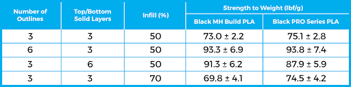
Including materials to printed components can improve the general power. The consumer can add outlines, prime/backside stable layers, or improve infill proportion, however which technique of addition is only in rising power? The Valpo group printed specimens with double the variety of outlines, double the stable layers on the highest/backside, and a rise to 70% infill. The worth of 70% infill is chosen because of the comparable specimen weight in comparison with the opposite two modified specimens.
Evaluation of the leads to Desk 7 demonstrates that a rise within the power to weight ratio is feasible with outlines and stable layers, however that rising the infill proportion didn’t have a statistically important impact. You will need to be aware that the kind of loading and print geometry is essential to the place materials ought to be added. Compressive masses or advanced geometry could shift the vital areas. Future exams with totally different loading configurations could shine gentle on these results.
Desk 7: Tensile power of specimens with added materials in numerous areas.
4.2.4 Infill
The earlier part evaluations the impact of a rise from 50% infill to 70% infill. Extra infill percentages should be investigated to find out if the rise in power follows a development.
Determine 15 shows p.c infill versus peak load for specimens present process tensile loading. This graph reveals that from 50% to 80% infill the slope for rising power is comparatively shallow; nevertheless, the slope is roughly 4 occasions larger above 80% infill. That is possible as a result of elevated bonding between infill traces. These outcomes will should be repeated for different geometries and masses, corresponding to pure compression, to definitively state a larger improve within the peak load is noticed for the 80-100% infill vary.

Determine 15: MatterHackers Black MH Construct PLA and Black PRO Collection PLA p.c infill versus peak load.
4.2.5 Print Velocity
Print pace is one other issue that usually has an impact on the consumer expertise. The power to print ever quicker is a requirement on the FFF business, however the impact of this improve in print pace on half power is typically neglected.
The Prusa i3 MK2 baseline specimens are all printed at 1800 mm/min with the intent of minimizing geometric errors. The printer is, nevertheless, able to printing quicker. Extra pace take a look at outcomes are proven in Determine 16. Black MH Construct PLA reveals no statistically important lower in power when rising the pace from 1800 to 3600 mm/min, however at 4800 mm/min the S-W ratio decreases by 8%. Black PRO Collection PLA S-W ratio barely will increase at 3600 mm/min, however just like MH Construct PLA it decreases at 4800 mm/min. Solely the tip consumer can decide if this lower in power is appropriate, and if there are extra beauty results from printing at these larger speeds. The impact of accelerating print pace will possible change based mostly on the geometric accuracy of printers at larger speeds, and on the flexibility of the hotend-nozzle mixture to switch enough power into the extruded filament.

Determine 16: Black MH Construct PLA and Black PRO Collection PLA print pace versus power.
4.3 Abstract of Take a look at Outcomes
Desk 8: Comparability of MatterHackers filaments.
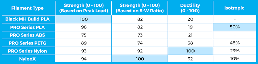
Desk 8 reveals the relative rankings of peak load, power to weight ratio, ductility, and isotropic (non-directionality of power). Analyzing the desk reveals that MH Construct PLA and PRO Collection PLA are glorious basic use filaments for the common consumer. They’ve excessive peak masses, and exhibit the perfect isotropic score. The principle downside is the comparatively brittle failure as in comparison with PRO Collection PETG and PRO Collection Nylon.
PRO Collection ABS carried out poorly within the tensile exams with the bottom peak load, S-W ratio, and comparatively low ductility. These outcomes, coupled with the problem of warping specimens, make it onerous to suggest ABS for this printer setup. The emission of styrene whereas printing ABS additional reduces the attractiveness of this filament sort [3]. The Valpo group believes that the appearance of newer filament sorts eliminates the necessity for ABS within the client printing market.
PRO Collection PETG outcomes characterize the fabric as a well-rounded filament. The filament is barely weaker than PLA, however with a ~100% improve within the pressure at failure. It has the second highest ductility score and the second highest isotropic score. There are nonetheless challenges related to printing in PETG, corresponding to the upper extrusion temperature, however total PETG has the potential to problem PLA as the first filament sort.
PRO Collection Nylon and NylonX are difficult filaments to print; nevertheless, additionally they include some distinctive advantages. If there’s a want for prints to exhibit excessive deformation with out failure, Nylon is the advised filament. NylonX however is extra appropriate for weight-dependent purposes, like customized drone components.
[3] P. Azimi, D. Zhao, C. Pouzet, et al., “Emissions of Ultrafine Particles and Risky Natural Compounds from Commercially Obtainable Desktop Three-Dimensional Printers with A number of Filaments,” Environmental Science and Expertise, Vol. 50, pp 1260-1268, Jan. 2016.
5. CONCLUSION
The analysis group at Valparaiso College is working to tell the buyer FFF neighborhood on how slicer settings, notably hotend temperature, have an effect on tensile properties of various filament supplies. The outcomes can dispel many conventional myths relating to client FFF printing, and they’ll hopefully assist each skilled and novice 3D printer customers in figuring out probably the most relevant filament for his or her undertaking. FFF printers have many variables that have an effect on half power exterior of simply the slicer settings; subsequently, it’s not advisable to make use of this knowledge to estimate the power of printed components. As a substitute, the analysis group suggests you take a look at the relative values to find out how totally different filament sorts will possible carry out by yourself printer. Probably the most acceptable slicer settings for different hotend fashions, filament diameters, nozzle diameters, and so on.… could differ extensively. The Valpo group hopes the outcomes offered on this report encourage customers to think about how all these variables may have an effect on printed components, and the group hopes future experiments will solely improve parameter consciousness.
The Valpo group is all the time in search of methods to help the buyer FFF neighborhood. You possibly can vote on the following space of analysis by visiting our social media accounts on the following web page!
ABOUT THE ACCELERATED 3D PRINTING LAB AND VALPARAISO UNIVERSITY
The Accelerated 3D Printing Lab is situated within the Faculty of Engineering at Valparaiso College. Engineering at Valpo is an undergraduate solely program that’s persistently ranked within the prime 20 undergraduate engineering applications within the nation by U.S. Information & World Report. The Accelerated 3D Printing Lab was established within the Summer season of 2018 to help Valpo’s additive manufacturing analysis. College students examine quite a lot of conventional and novel additive manufacturing strategies with the intent of open entry to the analysis.
ABOUT THE AUTHORS
Samuel Hart ’17 and Trevor Grey ’20 examined over 2000 specimens to find how slicer settings have an effect on the tensile power of components. The outcomes on this paper wouldn’t be potential with out their onerous work and dedication. Dr. Daniel Blood, Assistant Professor of Mechanical Engineering and Bioengineering at Valpo, oversaw the work carried out by Sam and Trevor.

Extra due to Kelsey Unser, Rima Miller, Tyler Smar, and William Foy for his or her assist in organising the analysis.
Valparaiso College Faculty of Engineering Web site
Accelerated 3D Printing Lab Fb: @Accelerated3DPrintingLab
Twitter: @printing_lab
SPECIAL THANKS TO DAVE GAYLORD AT MATTERHACKERS
The Valpo group appreciates MatterHackers’ donation of filament for these exams, and likewise for Dave’s invaluable enter on testing. All filaments examined on this report can be found at their on-line retailer.
Store 3D Printing:
www.matterhackers.com
MatterHackers Fb:
@MatterHackers
Twitter:
@MatterHackers
APPENDIX – SIMPLIFY3D SETTINGS